Lab 03 - Tenants
Lab 03 - Configure Tenants and Tenant Constructs
Context
Having completed the Fabric Policy configuration so that we have an operational Underlay (confusingly called "Overlay-1" as you will see when executing CLI commands) and set our Switch Policies (which define our switches) and Interface Policies, Profiles, and AEPs (which define interface behaviors and allowed encapsulations or Vlans) we now start to define the logical components that will make it very easy to secure hosts and services uniformly at scale without consideration of their IP addresses, rather via their EPG association.
This logical separation begins with one or more Tenants. The fabric comes "out of the box" with three Tenants.
- infra
- A Tenant container for the ACI Fabric Infrastructure
- mgmt
- Dedicated tenant for managing the ACI Fabric
- common
- A tenant with special properties so that any construct configured within this tenant is automatically available to any other Tenant created in the fabric.
- This tenant is very useful for shared services and you will often find an L3Out , VRF, and Bridge Domains which are shared across other Tenants configured in the common tenant.
Lab Goals
Tenant portion of the ACI Management Information Tree (MIT)
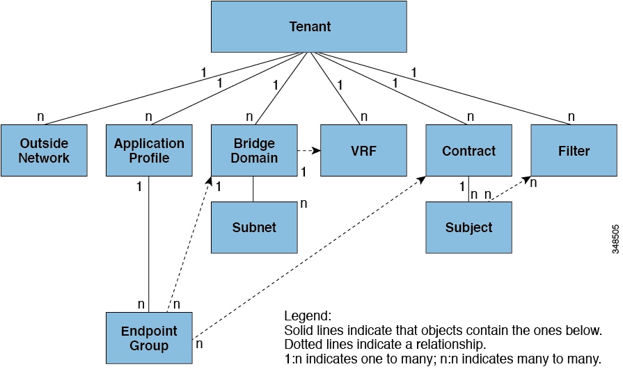
- Understand the relationships between the ACI Logical Constructs
- Step 1: Create a Tenant and VRF
- Step 2: Create a Bridge Domain and Subnets
- Step 3: Create an Application Profile and EPGs
- Step 4: Create Filters and Contracts
- Step 5: Apply Contracts to EPGs
This is the final "set up only" lab. At the completion of this lab, the fabric will be ready for actual traffic and connectivity.
The following constructs or objects will be configured in this lab:
| Object Type | Object Name | Function |
|---|---|---|
| Tenant | POD##_Tenant | Administrative domain containing all subsequent objects (VRFs, BDs, EPGs, Subnets, Application Profiles) |
| VRF | POD##_VRF | Layer 3 routing and forwarding domain within a tenant |
| Bridge Domain | POD##_BD | Logical container defining flooding behavior. Always associated with a single VRF and often associated with one ore more subnets. |
| Subnet | 10.0.1.254/24 | IP Subnet |
| Application Profile | Tiered_AppProfile | Container for EPGs and the policies which define associations, encapsulations, and interactions |
| EGP | - Web - App - DB |
Logical grouping of endpoints which have similar requirements, often security requirements. |
Reminder:
- ## = Your Pod Number. For example, if your Pod number is 11, then replace ## with 11 (POD11_Tenant)
It is important to think about how to consistently name your constructs. You have some flexibility in the lab but please keep in mind that the lab is shared and so you should always make sure your constructs can be associated to your tenant and your work.
Step 1 - Create a Tenant and VRF
A Tenant in ACI represents a management domain. Common tenants in actual deployments include tenants such as:
- Production
- Dev
- QA
- DMZ
As you can see from the MIT diagram, a Tenant contains one or more VRFs and so you often find that the Production tenant has a Production VRF associated with it. A VRF in ACI is a VRF. You cannot have overlapping IP Address space within an VRF and so the same is true for a VRF in ACI.
In the lab, each lab participant will create a tenant based on their Pod assignment (Pod number).
Navigate to Tenants > Add Tenant
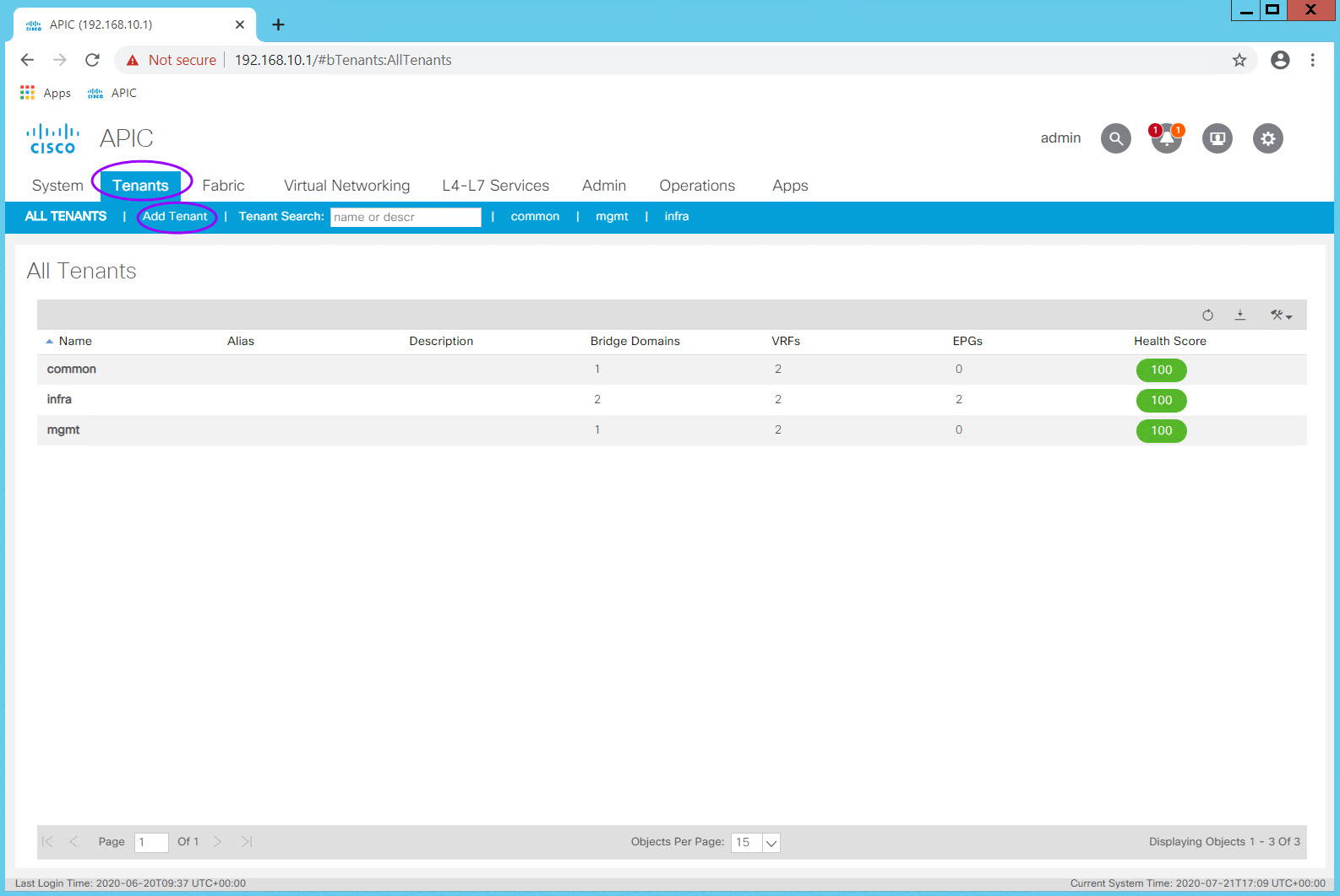
The Create Tenant dialog box will appear. The only required field is the Tenant name.
Enter your Tenant name in the Name field and click Submit.
Notice that here you can also associate a Monitoring Policy as well as Security Domains. If this Tenant had special access requirements, then here is where you can associate a specific Security Domain policy with the Tenant. This can be done after the Tenant is created.
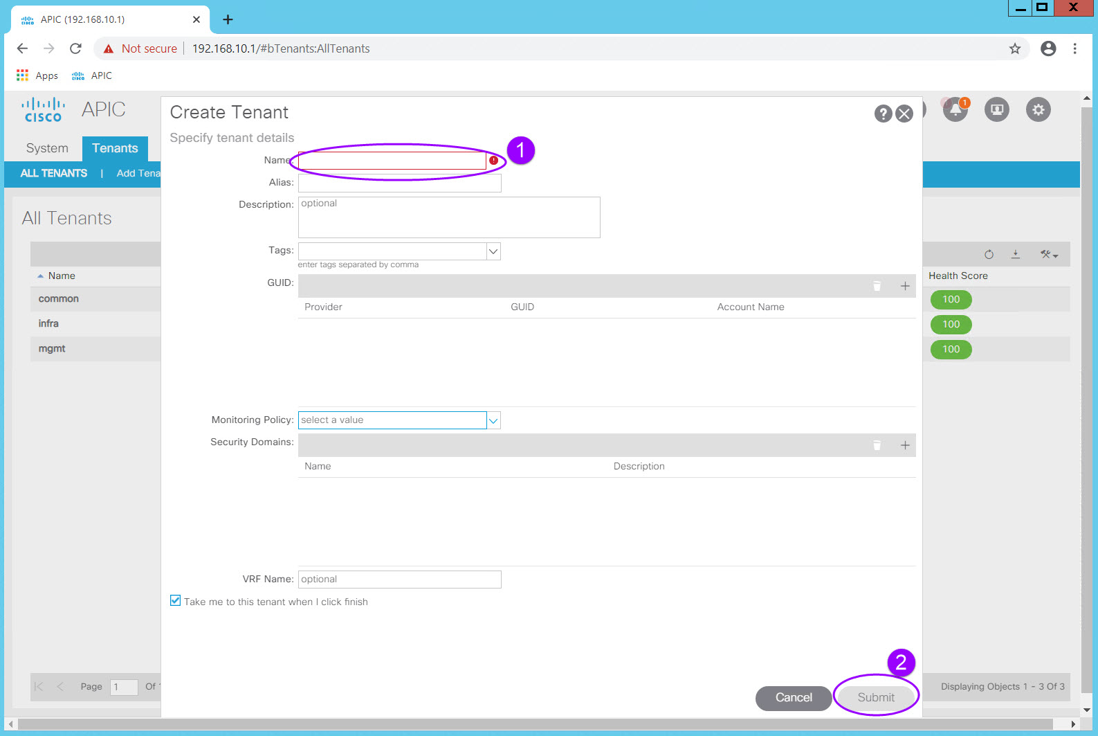
Because we left the "Take me to this tenant when I click finish" option checked, we will be taken to the new tenant page once Submit is clicked.
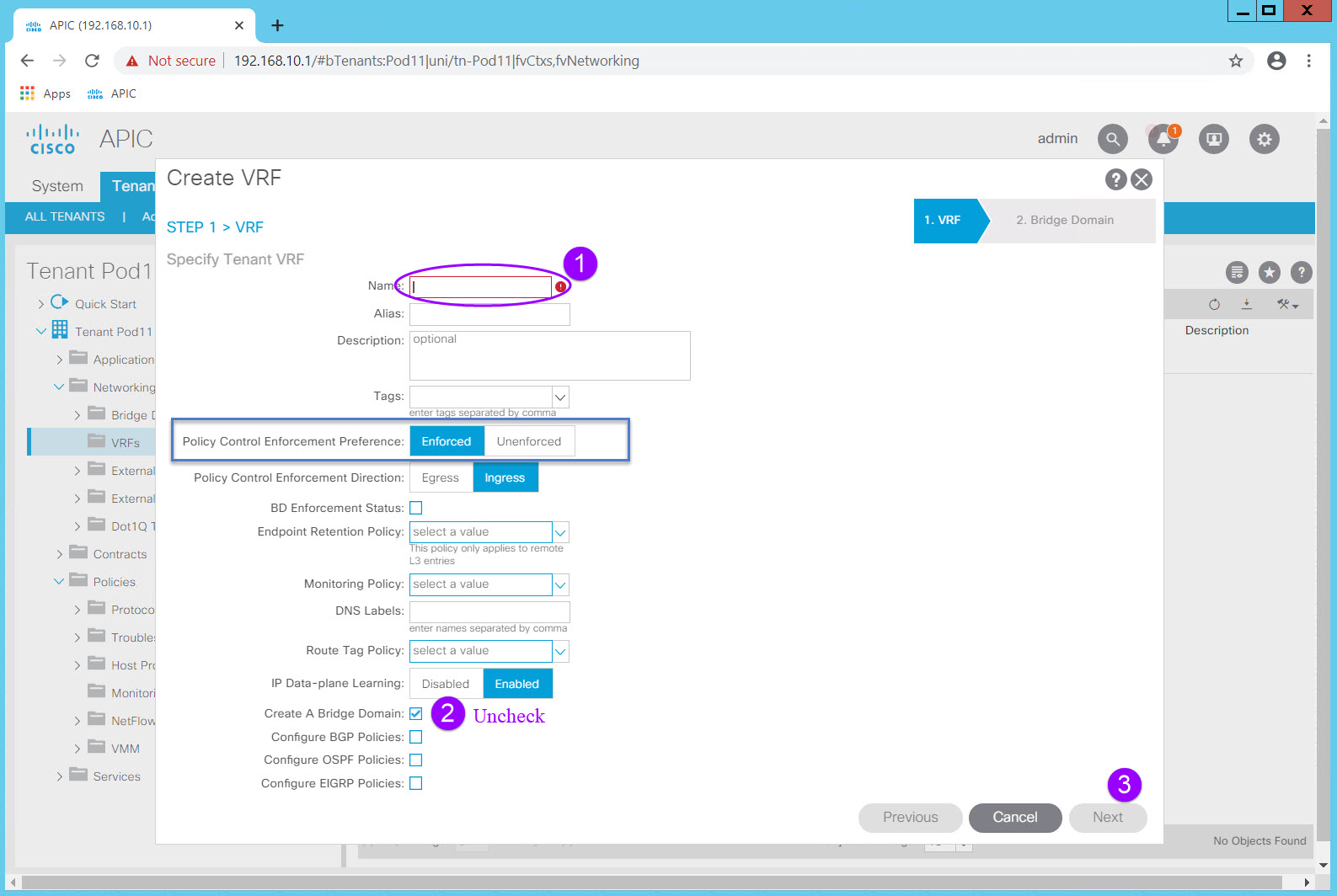
From here navigate to Networking > VRFs and right click on the VRF Folder icon. Select Create VRF and the Create VRF dialog will appear.
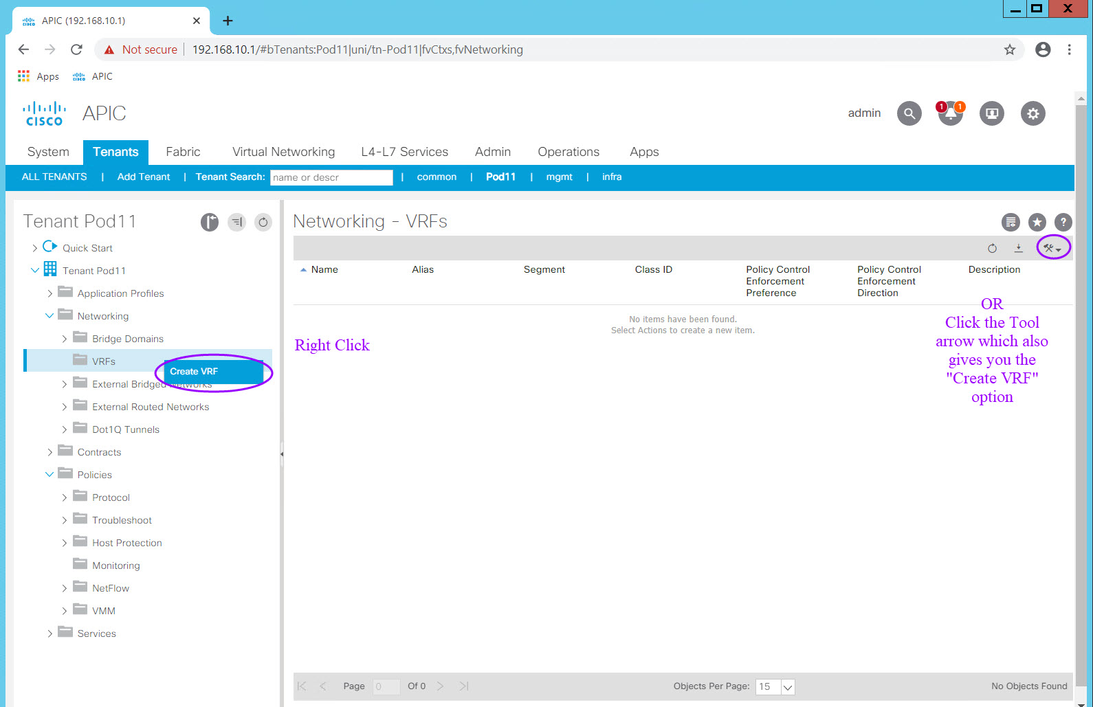
In the Create VRF dialog, enter the VRF name, uncheck the "Create A Bridge Domain" check box, and Click "Finish". Once you uncheck the "Create A Bridge Domain" check box the Next option becomes Finish as there is no next step. All other values remain unchanged and at their default settings.
As you know, ACI behaves in a default-deny, "white list" security model, so that only the required access is defined for connectivity. In a "black list" model, only the "bad" traffic is denied which assumes you know what the "bad" traffic is. The default-deny, only allow what is needed ("white list"), is by far the more secure. ACI does give you the option of disabling this behavior in several ways, one of which is here a the VRF level. Note that the Policy Control Enforcement Preference is Enforced by default. Should you have a need to disable this behavior (NOT RECOMMENDED), you can do so by setting Policy Control Enforcement Preference to Unenforced. This is rarely done in production but may be a useful troubleshooting tool.
Because this VRF was created within the Tenant context it is now associated with the Tenant.
Step 2: Create a Bridge Domain and Subnets
In traditional networking a Vlan inherently defines a broadcast domain, an encapsulation, and optionally a Layer 3 subnet.
We don't typically think of all of those items as separate functions but in ACI you must.
In its basic form, a Bridge Domain (BD) defines a broadcast domain as well as flooding behavior. We don't call this out specifically in traditional network because we don't have any other options for flooding behavior, but in ACI we do. ACI can optimize flooding behavior and reduce broadcasts and so a Bridge Domain allows you to define how you want flooding to behave for a particular Bridge Domain.
It is also common to define a subnet within the Bridge Domain thereby creating the foundation for a Layer 3 "Vlan".
Notice that you don't define the encapsulation within the BD. That takes place within an EPG either statically or dynamically depending on the need and the associated Domains (Physical, VMM).
A BD can have multiple subnets and contains settings which instantiate the subnet's gateway on the ACI Fabric.
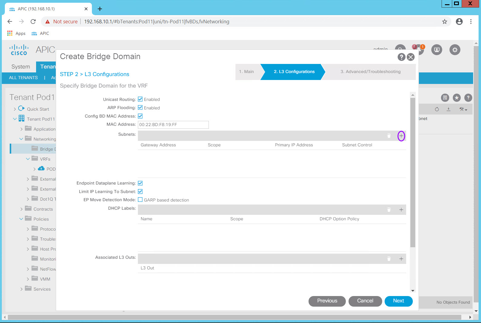
Step 2.1 - Create Bridge Domain
Navigate to Tenants > PODXX_Tenant > Networking > Bridge Domains and right click on the Bridge Domain Folder icon. Select Create Bridge Domain and the Create Bridge Domain dialog will appear.
Name: PODXX_BD
VRF: PODXX_VRF (PODXX_Tenant)
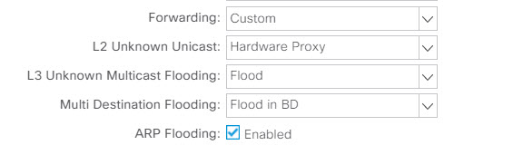
Forwarding: Cusom (change from the default Optimize)
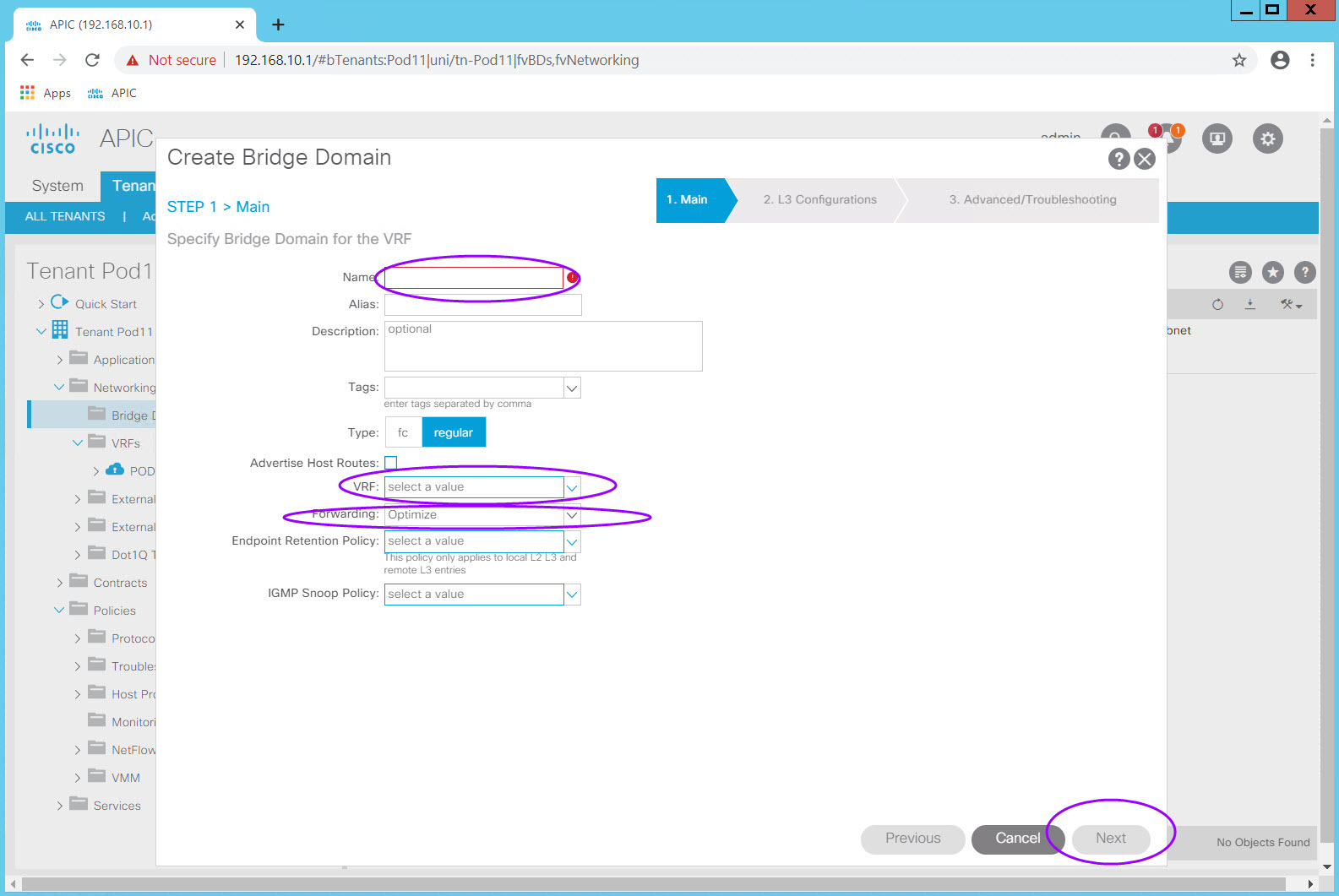
Select Custom in the Forwarding: drop down
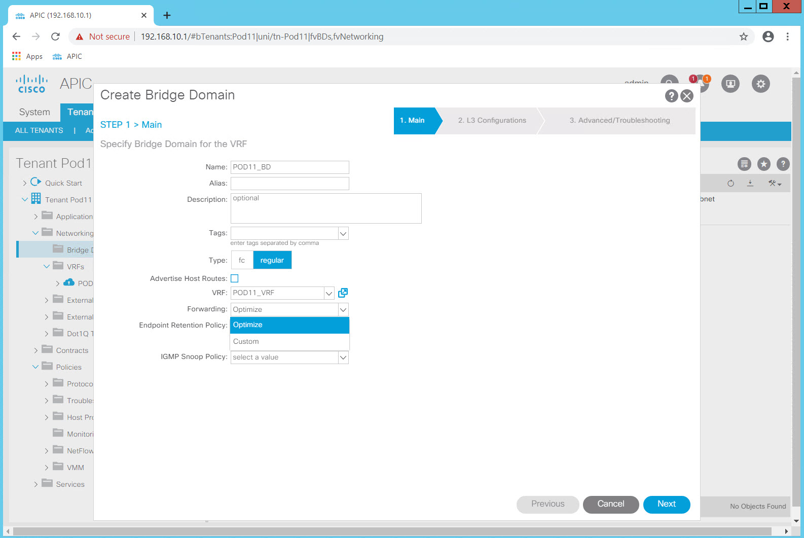
Click Next
Step 2.2 - Create Subnets
As with any data center it is important to consider the subnetting design.
With ACI, taking a more network centric approach, each BD can be associated with one subnet, simulating what we are used to today. One Bridge Domain, advertising one subnet and associated with one EPG and one encapsulation mimics an SVI in todays networking.
In the Lab, we will model a more powerful approach, to give you a sense of what can be accomplished with the flexibility of ACI.
In our design we will have one Bridge Domain, and within that BD we will instantiate the three subnets we require for our data center Virtual Machines.
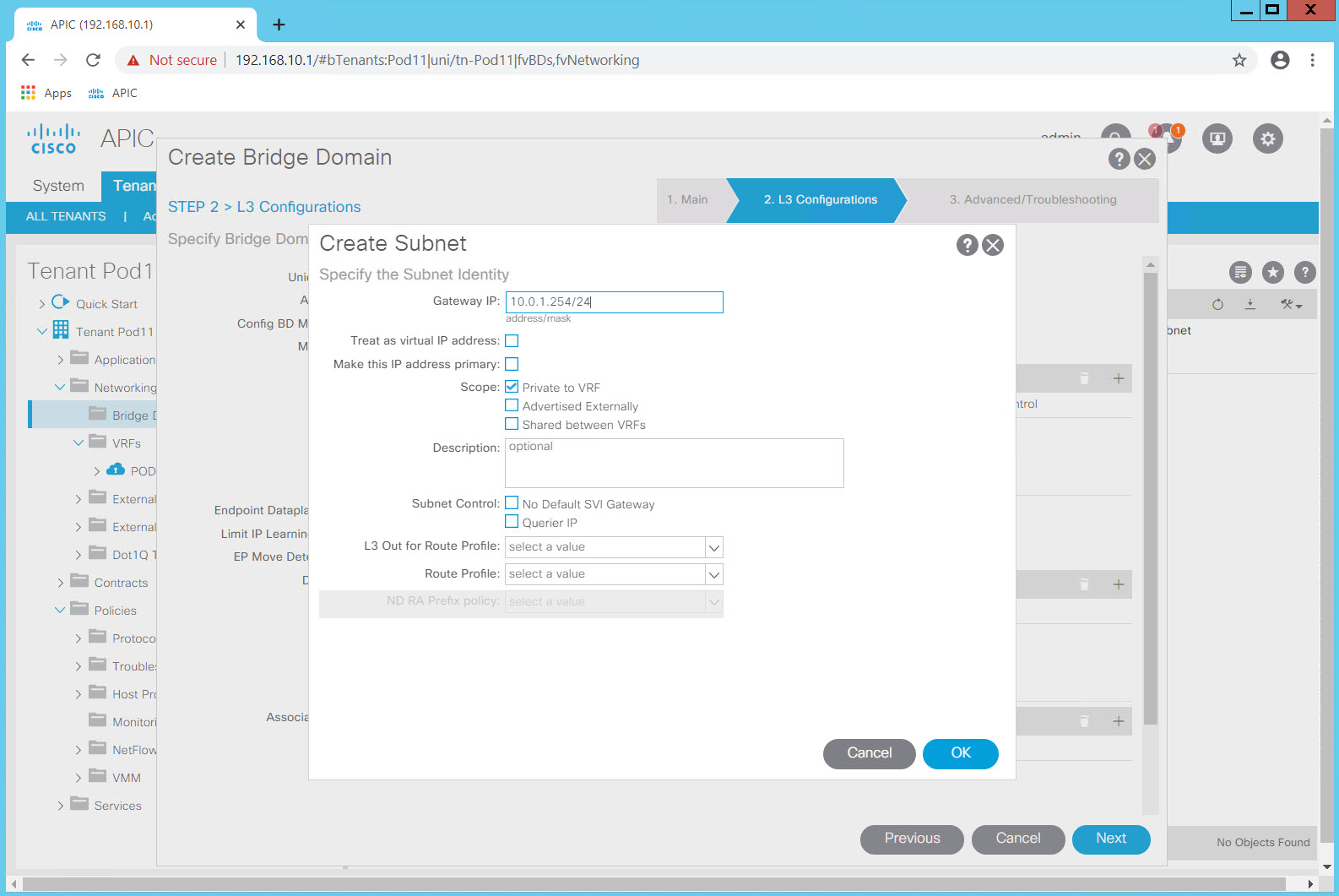
Subnet Design for POD##:
| Subnet | Gateway IP: (Anycast Gateway)* | Use |
|---|---|---|
| 10.0.1.0/24 | 10.0.1.254/24 | |
| 10.0.2.0/24 | 10.0.2.254/24 | |
| 10.0.3.0/24 | 10.0.3.254/24 |
* Note: The Gateway IP: is exactly that, defining both the subnet and mask and the anycast gateway IP. (.254 for all subnets).
Also, consider that each student is configuring the same subnets for their VMs. This is possible because each student has their own Tenant and VRF.
Click the plus (+) in the Subnets: table to add the three subnets in listed in the table.
Leave all other settings at their default values and click OK to advance to the "Step 3 Troubleshooting" screen.
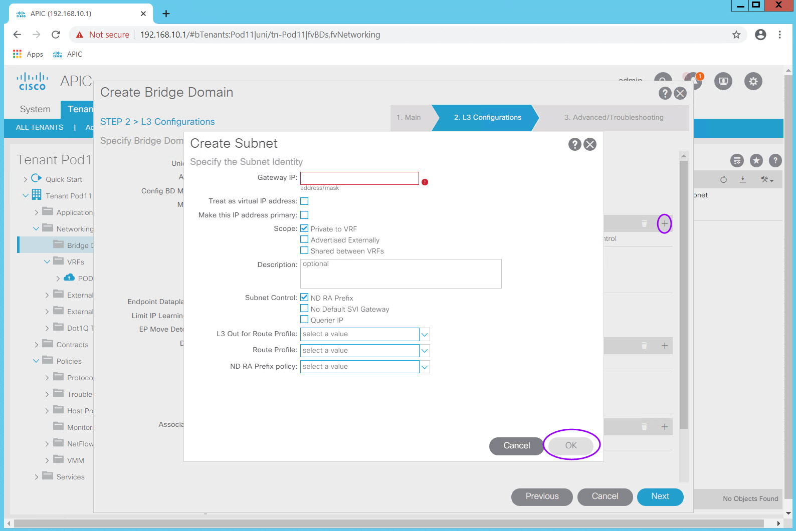
Note the options for Scope:.
| Scope: | When to use... |
|---|---|
| Private to VRF (Default) | |
| Advertised Externally | |
| Share between vRF |
Click OK
Make no changes to the "STEP 3 > Advanced/Troubleshooting" section and click Finish.
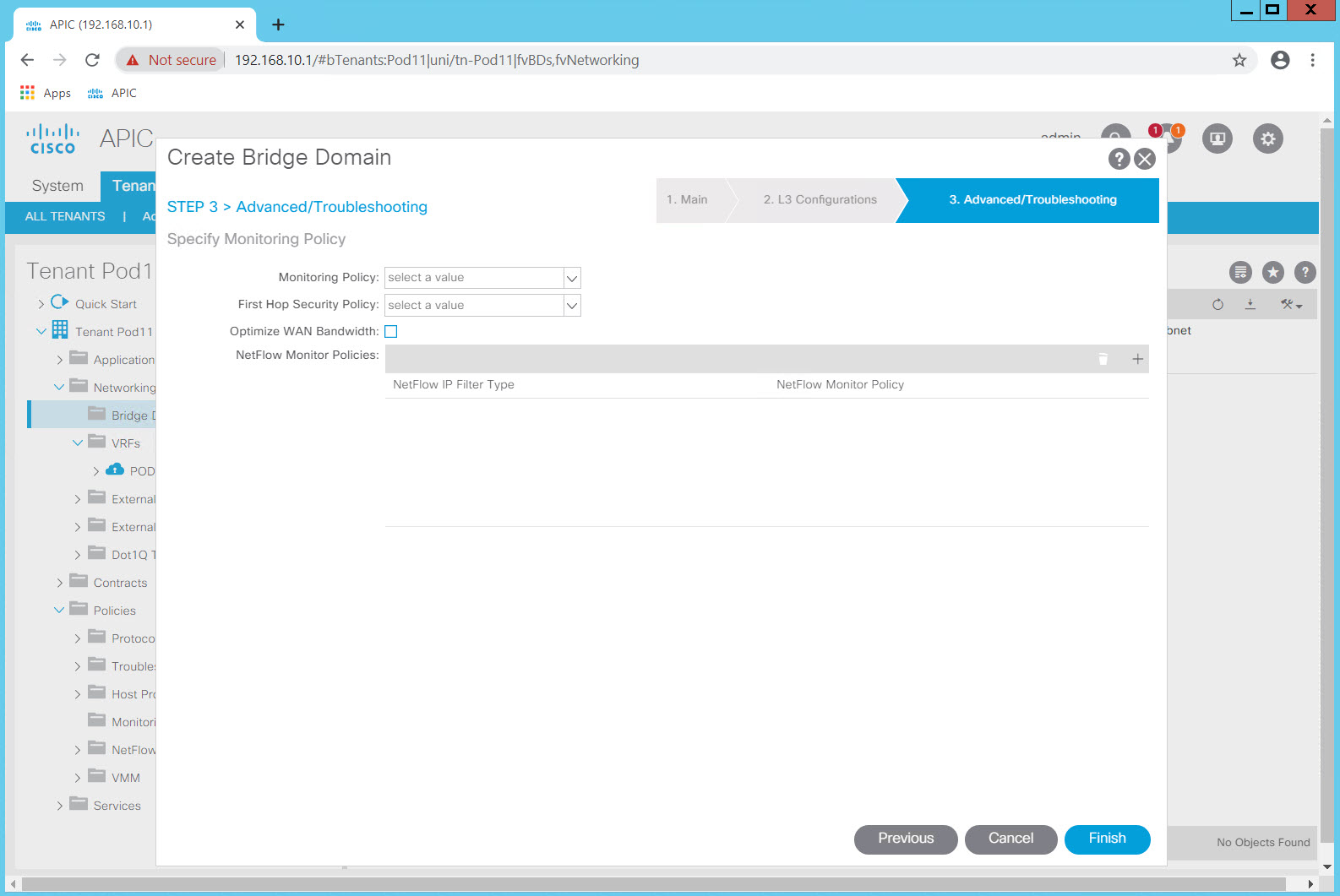
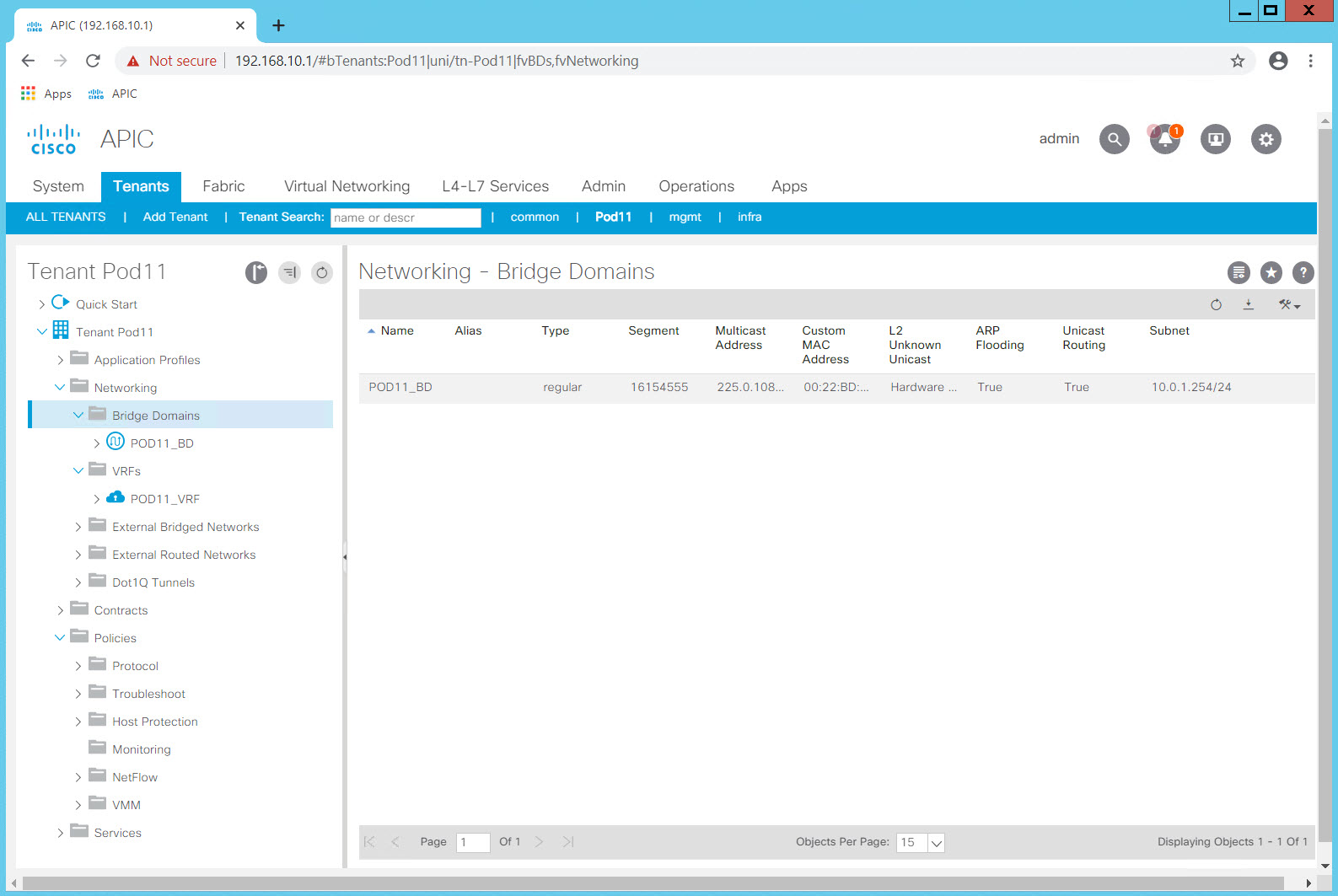
Review the list of Bridge Domains. You have configured a single BD in your tenant which contains three subnets. The BD is configured to flood in the "classical" way rather than the optimized way ACI can also support.
Step 3: Create an Application Profile and EPGs
An Application Profile is on organizational or grouping construct only. It is a container or folder for EPGs and their associations.
An EndPoint Group (EPG) is a container for endpoints that share some commonality. In many cases, these are endpoints that share a common security profile. This is an important distinction to make because Contracts (think of these as ACLs which act on EPGs rather than subnets and IP addresses) are applied to EPGs.
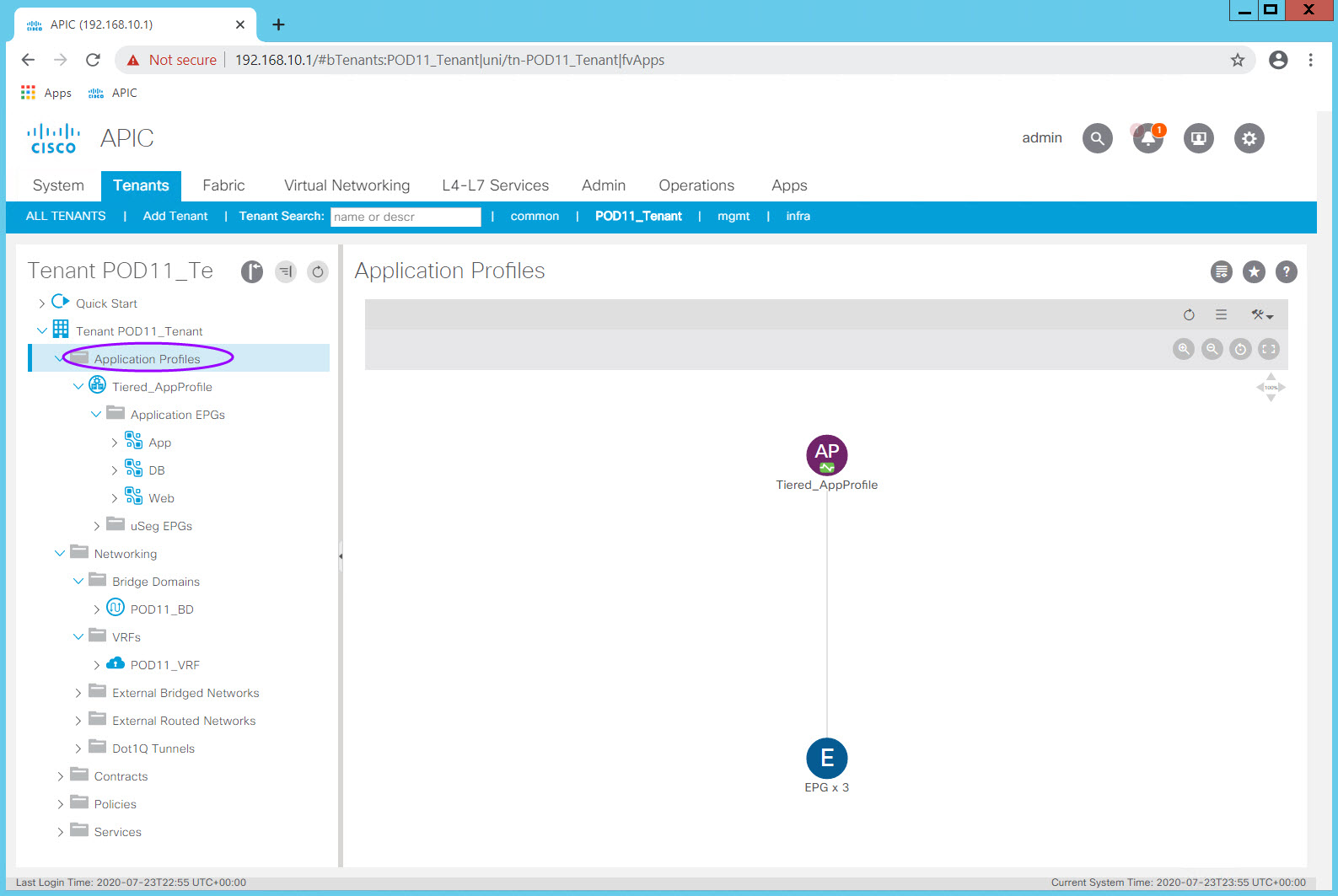
Navigate to Tenants > PODXX_Tenant > Application Profiles and right click on the Application Profiles Folder icon.
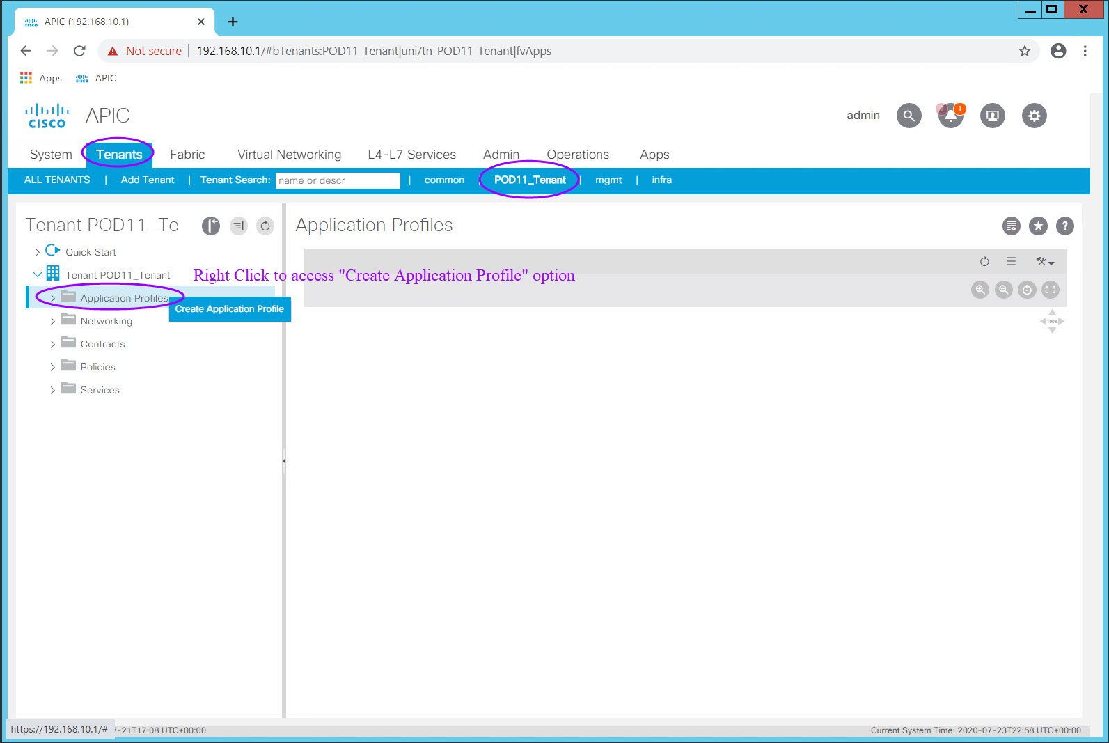
Select Create Application Profile and the Create Application Profile dialog will appear. Enter the Application Profile Name in the Name: field and click Submit.
You now have a container for your EPGs and their associated constructs.
From here, expand the Application Profile folder by clicking on the ">" symbol.

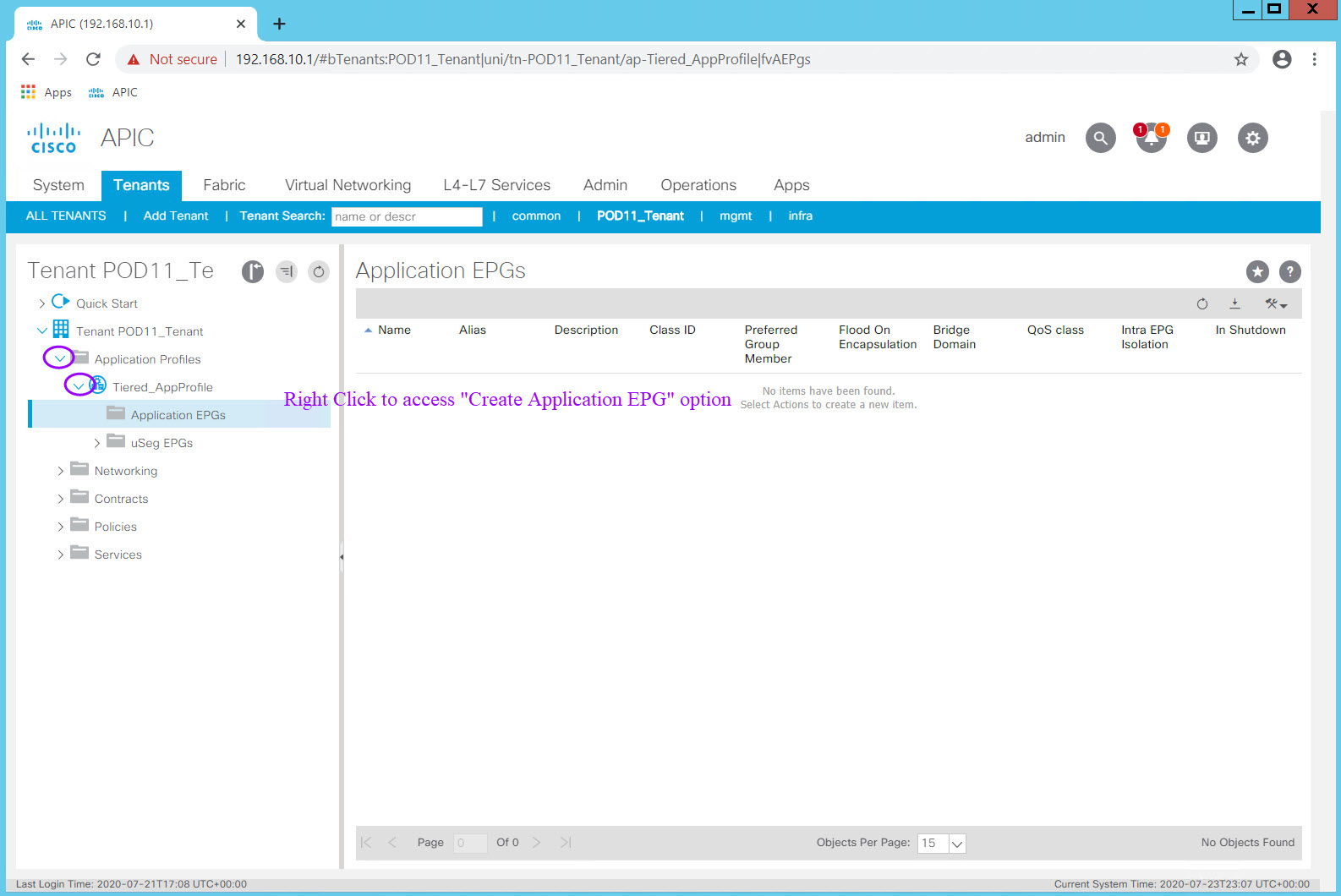
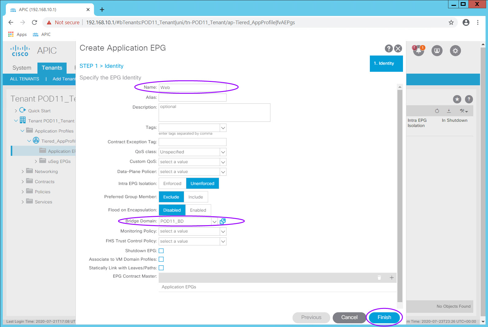
Expand your Application Profile Tiered_AppProfile and right click on the Application EPGs folder icon for the "Create Application EPG" option.
Remember the Tenant portion of the ACI Management Information Tree (MIT). Notice that an EPG must be associated to
- one Application Profile (which is associated to one Tenant)
- one Bridge Domain (which is associated to one VRF)
At a minimum those objects must be defined in order to create an EPG. Other EPG attributes such as Contracts and VM Domain profiles can be configured at a later time.
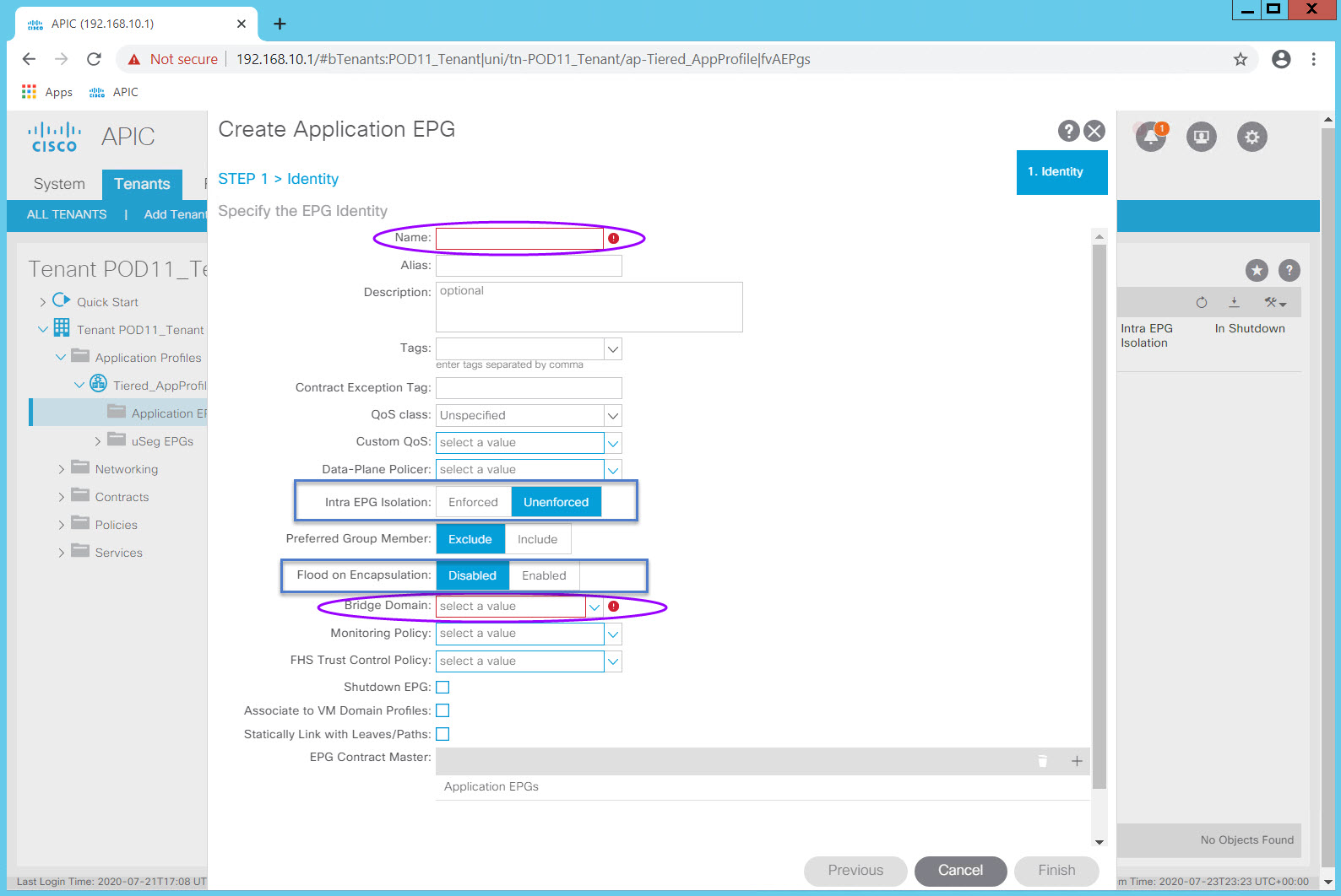
Enter the EPG name in the Name: field. Select the Bridge Domain in the Bridge Domain: field and click Finish.
Accept all the default values.
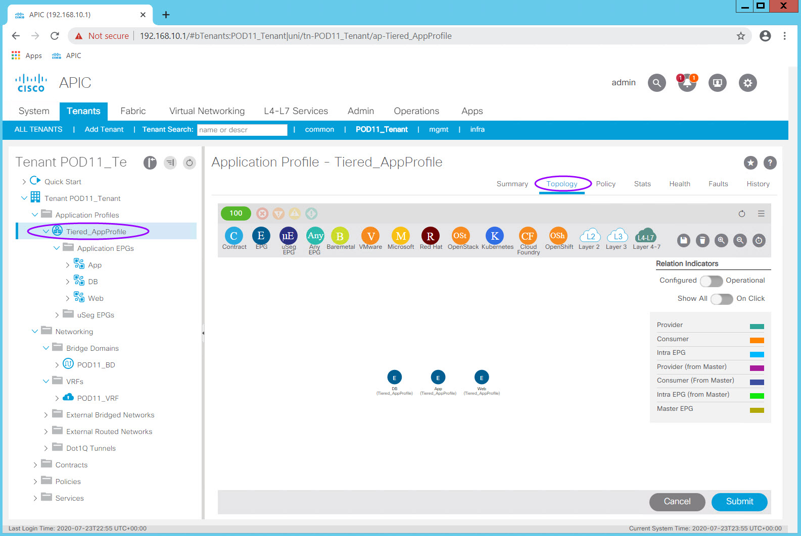
Using this same process, create two additional EPGs within this Application Profile, mapped to your PODXX_BD Bridge Domain.
- App
- DB
Step 4: Create Filters and Contracts
Contracts, and how they behave, make ACI one of the easiest fabrics to secure. Think of them as Access Control Lists which can be applied anywhere across the fabric (across all of your top of rack Leaf switches) and which are independent of a vlan or IP Subnet/Address.
A Cisco ACI filter is a TCP/IP header field, such as a Layer 3 protocol type or Layer 4 ports, that are used to allow inbound or outbound communications between EPGs.
A Cisco ACI contract defines the rules that specify what and how communication in a network is allowed. In Cisco ACI, contracts specify how communications between EPGs take place. Contract scope can be limited to the EPGs in an application profile, a tenant, a VRF, or the entire fabric. It is important to understand the impact scope can have on access.
Contracts are wholly logical constructs and so there is no Physical Layer configuration.
Contracts defined in the common tenant can be used across any Tenant like other constructs defined in the common tenant.
You will configure three filters and use them as building blocks for defining contracts between EPGs.
- Basic Filter
- Allow ICMP and SSH
- HTTP Filter
- Allow HTTP
- FTP Filter
- Allow FTP
A few naming Tips:
Start the name with protocol/port as that is what typically appears to reduce ambiguity
If you are going to do Taboo (not recommended) or Deny contracts, consider adding the action to the Subject name.
For example: TCP_22_Permit_SSH_Subject. If you will not use these then establish the convention that all Subjects are "Permit".Consider adding Source or Destination (For example: TCP_9004_DST_Entry)
Example Object Names:
- TCP_9004_Filter
- TCP_9004_Entry
- PKI_BIDi_Contract
- TCP_22_SSH_Subject
For the lab we will use a simplified naming convention.
Filter Table
| Filter Name | Entry Name | EtherType | IP Protocol | Source Port_Range From - To |
Destination Port_Range From - To |
|---|---|---|---|---|---|
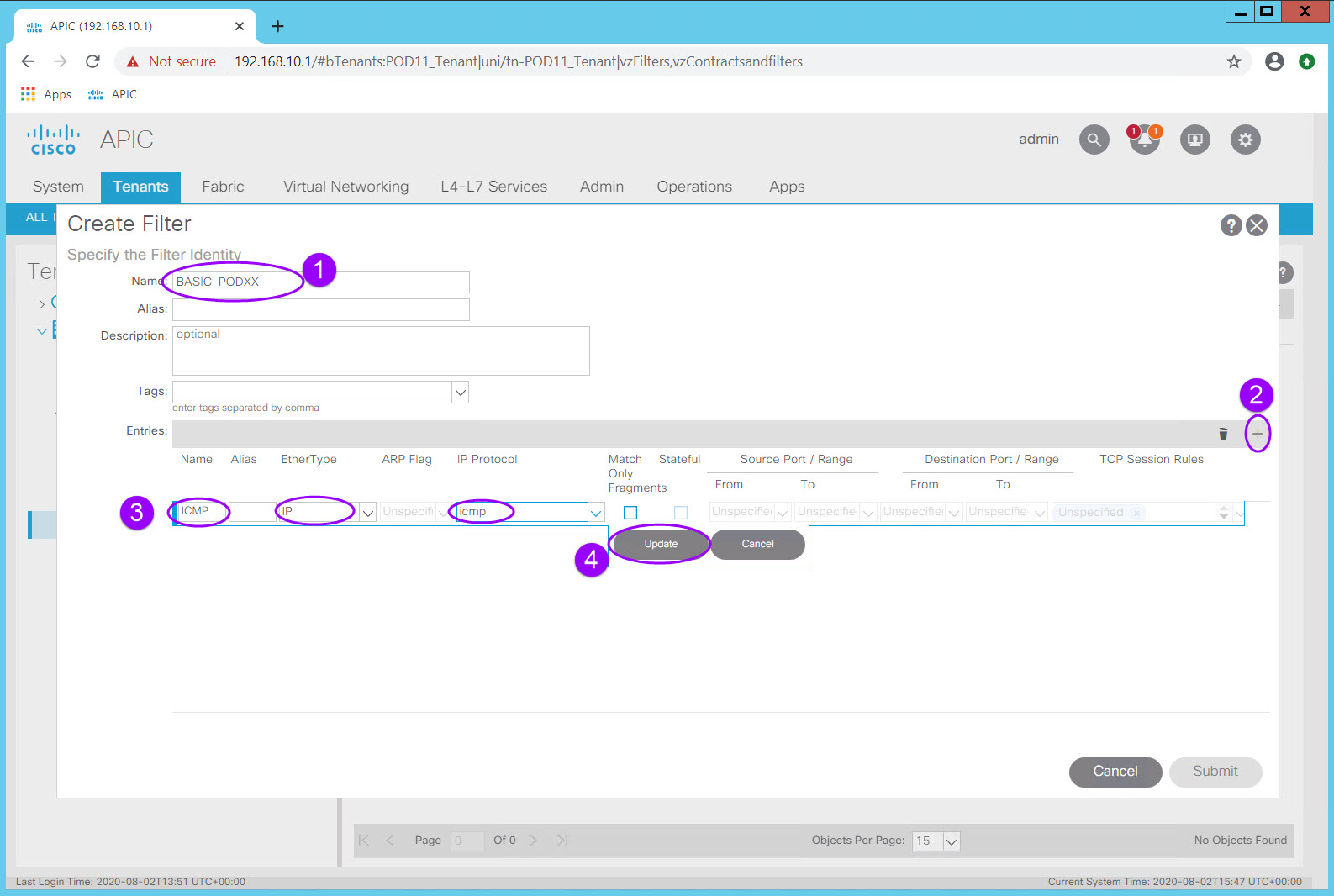
| BASIC-POD## | ICMP | IP | icmp | Leave blank | Leave blank |
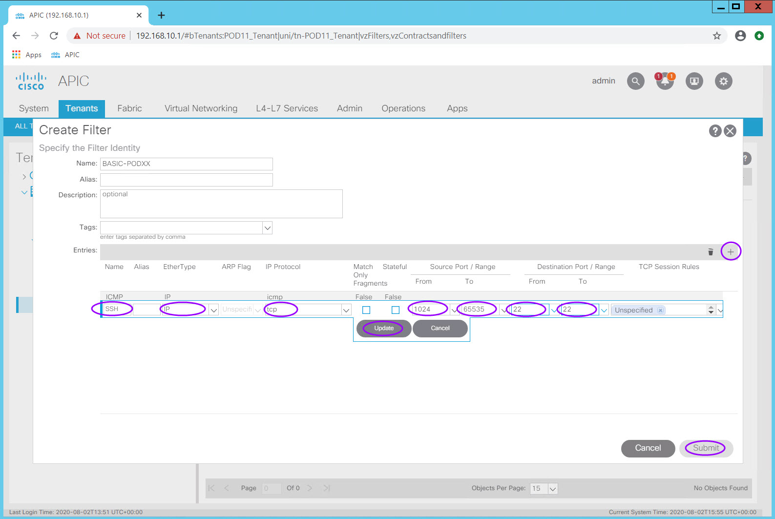
| BASIC-POD## (second entry) | SSH | IP | tcp | 1024 - 65535 | 22 - 22 |
| HTTP-POD## | HTTP | IP | tcp | 1024 - 65535 | 80 - 80 (http - http also works) |
| FTP-POD## | FTP | IP | tcp | 1024 - 65535 | 21 - 21 |
Step 4.1 Basic Filter for Ping (ICMP) and SSH
Within your Tenant, navigate to Contracts > Filters
Right-click Filters and choose Create Filters
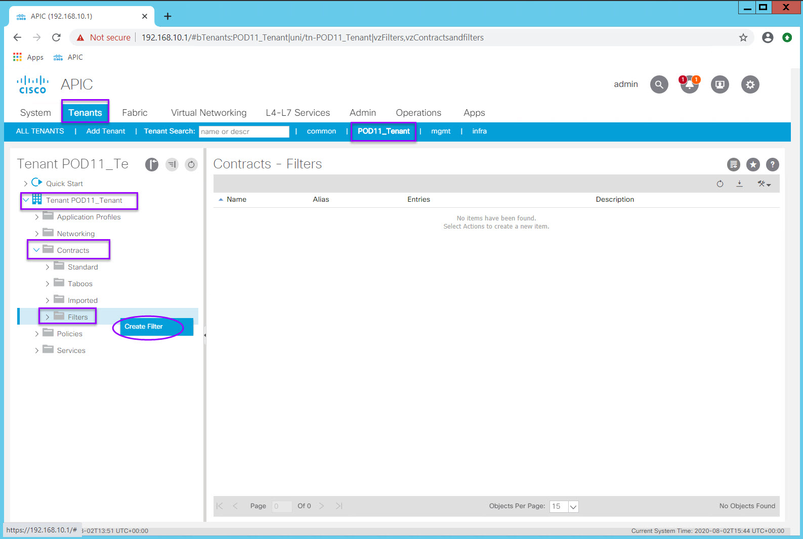
- Create a filter named BASIC-POD##
- Click the plus sign (+) to add an Entry (again, think of this as a single Access List Entry).
- Complete the first entry which you will name ICMP per the table above
- Click the Update button for your entry row.
This filter will have two entries, ICMP and SSH
Click the plus sign again to add the second SSH entry.
Click Update and Submit
Step 4.2 HTTP Filter for HTTP
Using the procedure above and the information in the Filter Table, create an HTTP filter.
Step 4.3 FTP Filter for FTP
Using the procedure above and the information in the Filter Table, create an FTP filter.
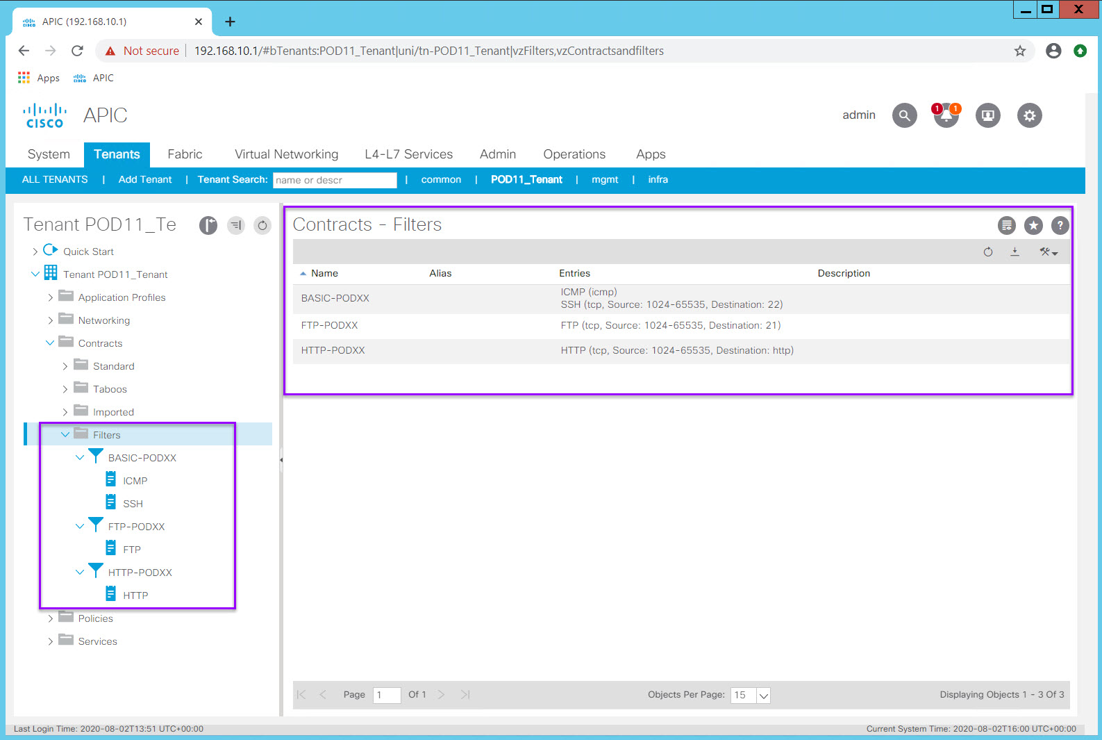
Once you complete all of the filters in the Filter Table, you should be able to expand all the objects in the Filter folder and should resemble this:
Step 4.4 Contracts
Contracts provide a way to control traffic flow within the ACI fabric between endpoint groups. Because ACI operates by default in a white list mode, without contracts there is no communication between EPGs. These contracts are built using a provider-consumer model where one endpoint group provides the services it wants to offer (servers) and another endpoint group consumes them (servers or clients). Contracts are assigned a scope of Global, Tenant, VRF, or Application Profile, which limit the accessibility of the contract. The default scope is VRF.Exter
Contracts consist of:
- Subjects - One or more subjects can be associated with a Contract. A subject has a name, a filter, and an action (Permit or Deny). A Subject also has a shortcut to support bidirectional (Apply Both Directions and Reverse Filter Ports).
- Filters - a Subject can have 1 or more filters. Think of the Filter as an ACE or Entry within an ACL.
A Contract in ACI will define the permitted (white list) communication between its associated EPGs. Again, think of the Filters as Access Control Entries (ACE) and the Contract as an Access Control List (ACL). The biggest difference you will see, is that there are no vlans or IP Subnets or Host IP Addresses in these configurations.
With the Filters you have defined, you have port/protocol objects which you can now bundle together and apply in whichever direction is appropriate to EPGs.POD
You will create two Contracts Using these FIlter Objects.
Contract Table
| Contract Name | Subject Name | Apply Both Directions Checkbox | Reverse Filters Ports Checkbox | Filter Name (Select Existing form Drop Down) | Action |
|---|---|---|---|---|---|
| WebAccess-POD## | WEB-ACCESS | Checked (Default) | Checked (Default) | PODXX/BASIC-PODXX | Permit |
| WebAccess-POD## | WEB-ACCESS (Second Entry) | Checked (Default) | Checked (Default) | PODXX/HTTP-PODXX | Permit |
| FileAccess-POD## | FILE-ACCESS | Checked (Default) | Checked (Default) | PODXX/BASIC-PODX | Permit |
| FileAccess-POD## | FILE-ACCESS (Second Entry) | Checked (Default) | Checked (Default) | PODXX/FTP-PODXX | Permit |
Directives Leave blank for all (Default)
Priority- Leave blank for all (Default)
Step 4.4.1 Web Access Contract
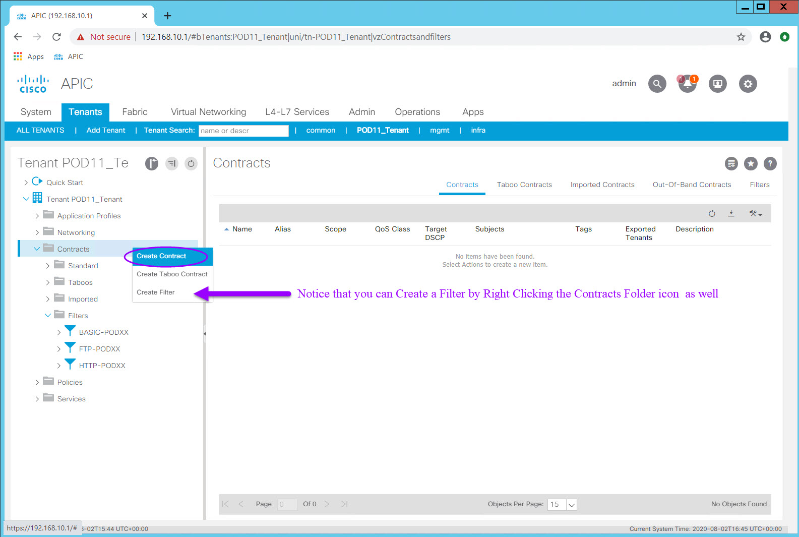
Within your Tenant, navigate to Contracts
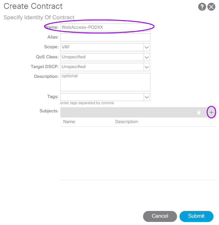
Right-click Contracts folder icon and choose Create Contract
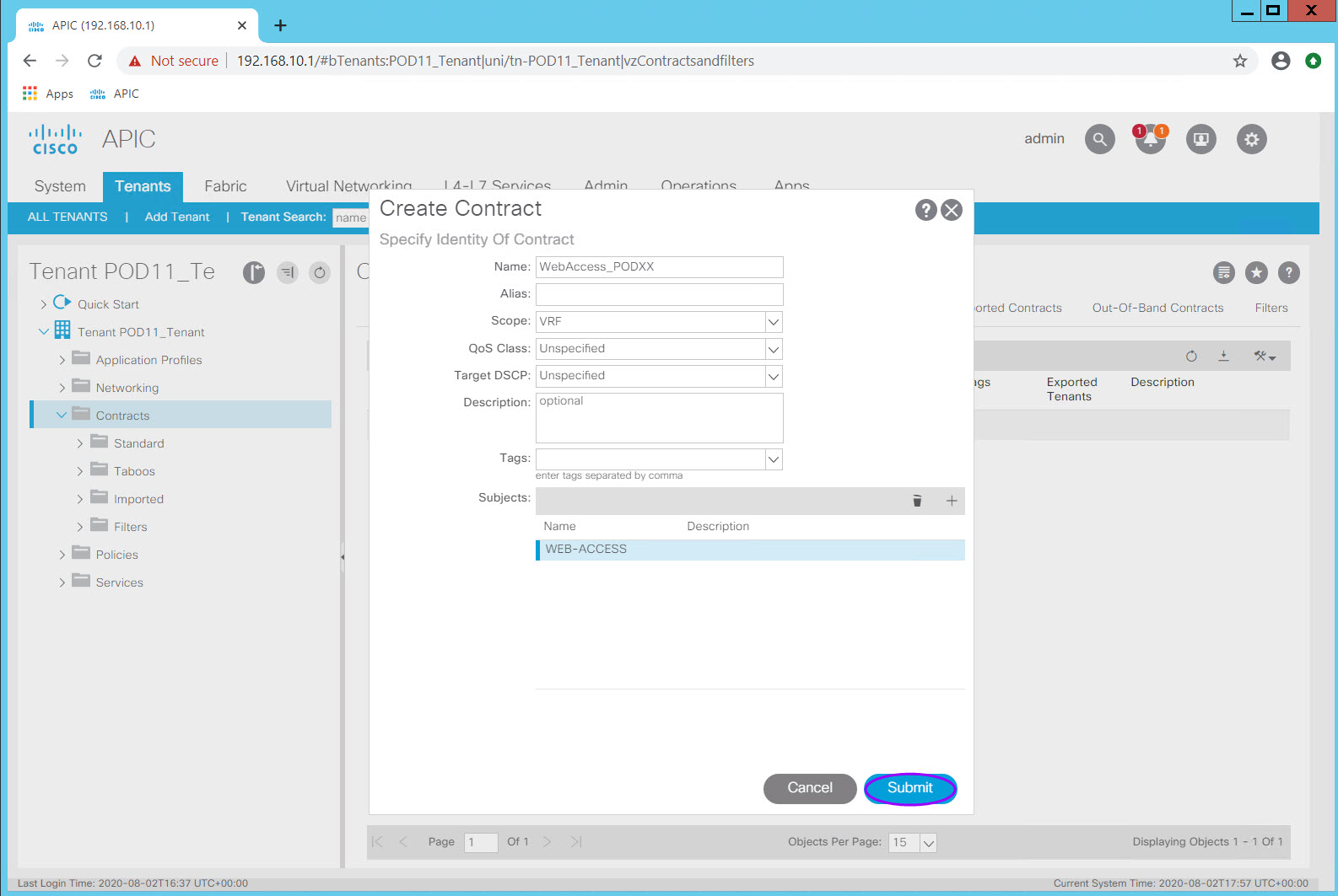
- Create a contract named WebAccess-POD##. Accept all the defaults including the Scope (VRF).
- Click the plus sign (+) in the Subjects: section to create a subject and add Filters.
- Add Filters using the previously created filters per the table above
- Click the Update button for your entry row.
\scripts\training\2020\aci4_labguide\docs\images\03_04-4-ContractCreateDialog-Subject.jpg)
- Click OK to return to the Contract dialog
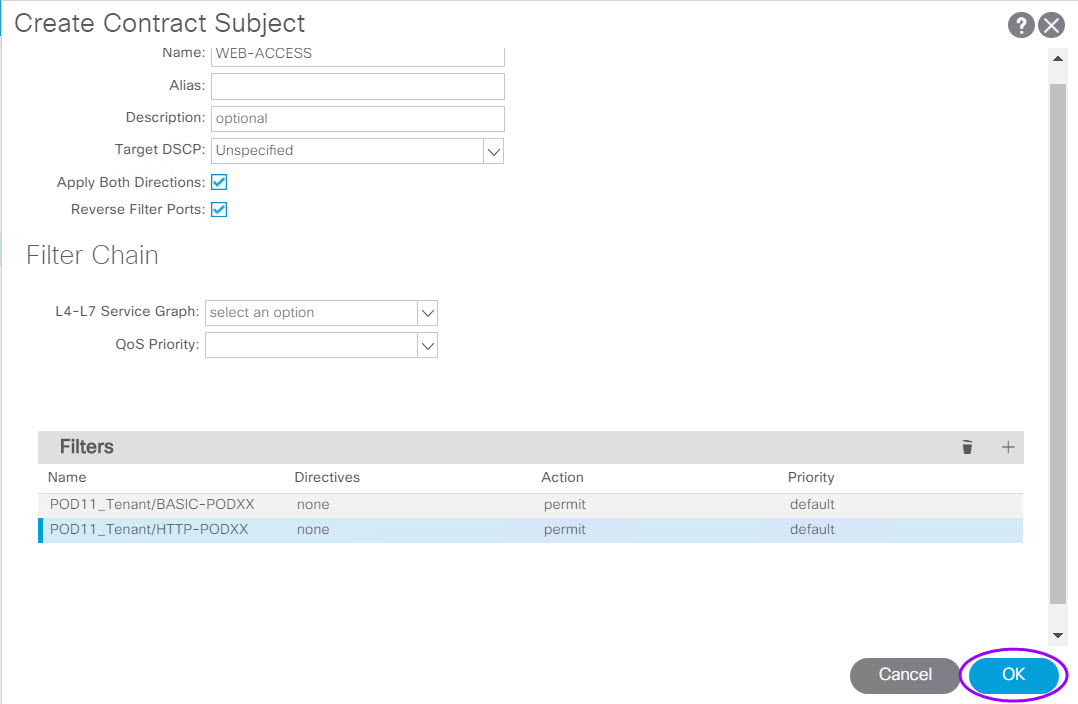
- Click Submit to complete the contract
Step 4.4.2 File Access Contract
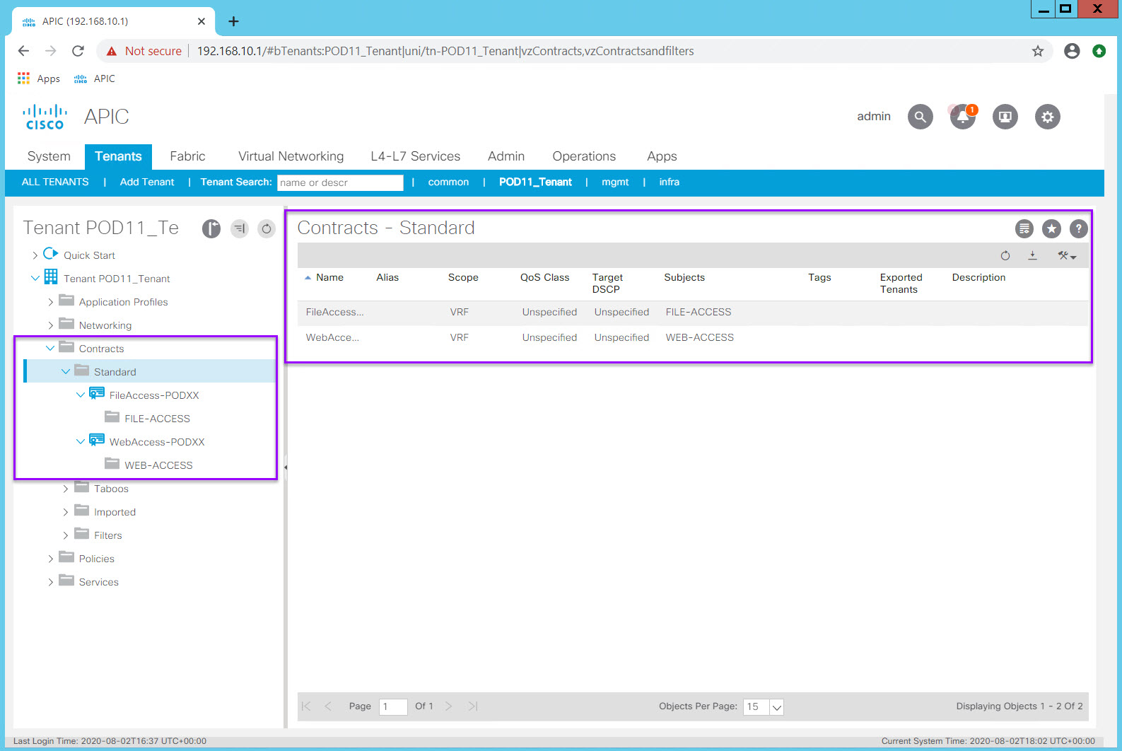
Using the procedure above and the information in the Contract Table, create the File Access Contract.
Upon completion of the two Contracts, your Contracts section should look like below:
Step 5: Apply Contracts to EPGs
Just as with ACLs its a good idea to make sure you understand the application flows.
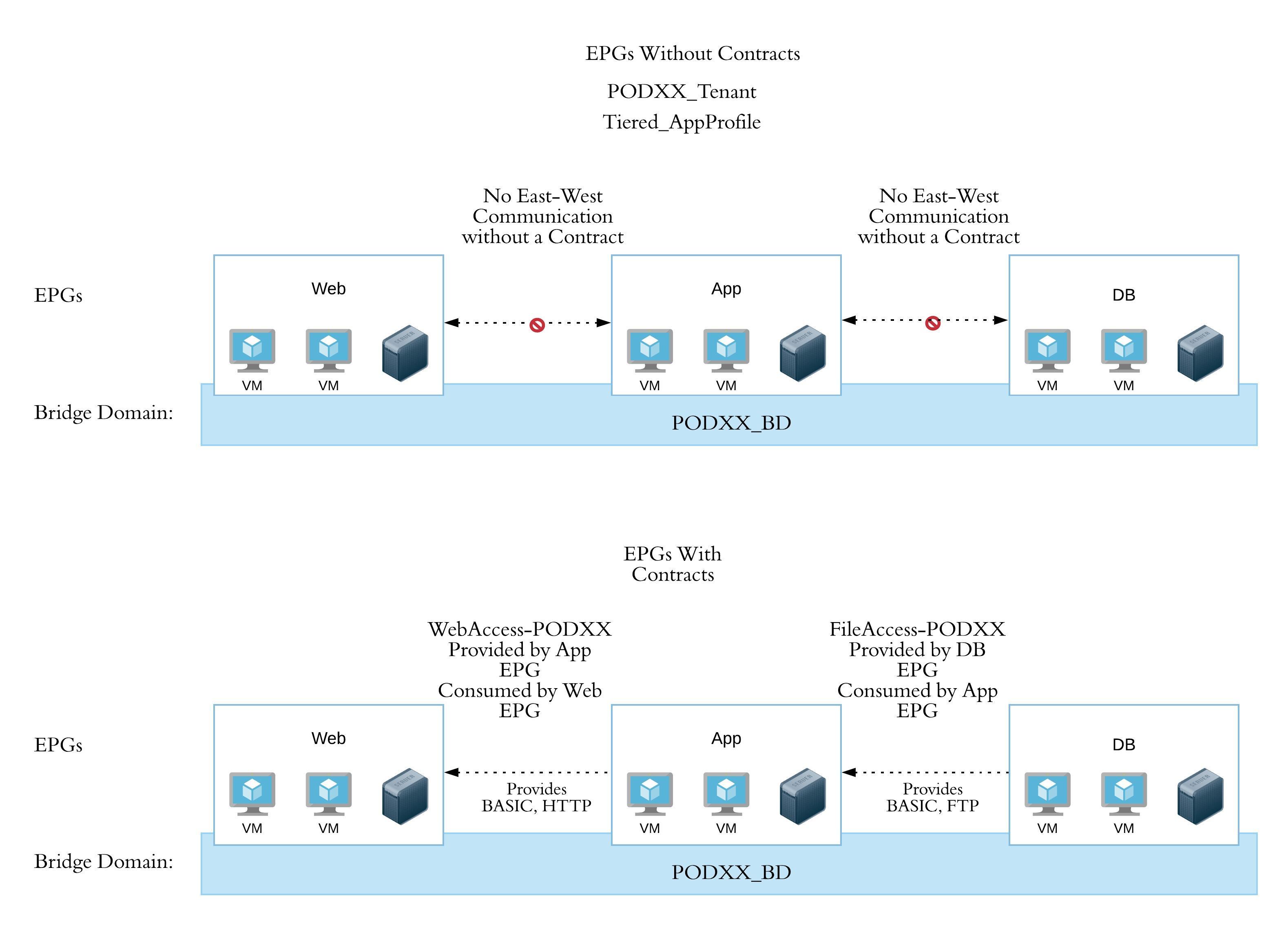
In ACI the terminology may add confusion at first. Just remember that 'Providing' a Contract means providing a service (like TCP/80 inbound) and 'Consuming' a contract allows an EPG to connect to a provided service.
Without contracts the endpoints in our EPGs have no connectivity outside their EPG.
When we apply our new Contracts we want the endpoints in the App EPG to provide HTTP, ICMP, and SSH to the endpoints in the Web EPG. We also want the endpoints (databases and file servers) in the DB EPG to provide FTP, ICMP, and SSH services to the endpoints in the App EPG.
Step 5.1 Apply the WebAccess-PODXX contract as a Provided Contract to the App EPG
Navigate to PODXX_Tenant > and expand Tiered-App > Application EPGs > App > Contracts
Right click on the Contracts Folder icon and select Add Provided Contract
Select WebAccess-POD## contract. No other changes are necessary
Click Submit
Examine the visual relationship by clicking on your Tiered-App Application Profile
Step 5.2 Apply the FileAccess-PODXX contract as a Provided Contract to the DB EPG
Use the procedure above to apply the FileAccess-POD## contract as a Provided Contract of the DB EPG.
Check in
This is quite a long lab so lets check in to see what we have accomplished and what functionality we should have.
Once this Lab is complete you should have:
- A Tenant and associated VRF
- A Bridge Domain containing three subnets associated with the VRF
- An Application Profile "container" with three EPGs all mapped to the Bridge Domain (one BD but three subnets)
- Filters describing
- ICMP
- SSH
- HTTP
- FTP
- Two contracts describing
- the allowed connectivity between the App EPG and the Web EPG utilizing the appropriate Filters
- the allowed connectivity between the APP EPG and the DB EPG utilizing the appropriate Filters
- The contracts applied to the appropriate EPGs in the appropriate direction ( Provider - Server and Server Services and Consumer - Clients)
The necessary Tenant-level logical components have now been created however a few steps remain to achieve connectivity external to the fabric and to Virtualized Hosts and Virtual Machines.